


- 트위터,페이스북


- HOME
- Customer Center
- FAQ

hit : 2,528


| title | [Sensor] I am curious about 3 axis acceleration sensor. |
|---|---|
| name | admin 11-08-29 21:44 |
Hello, customer? Thank you for using our NEWTC product. Detailed information is available at
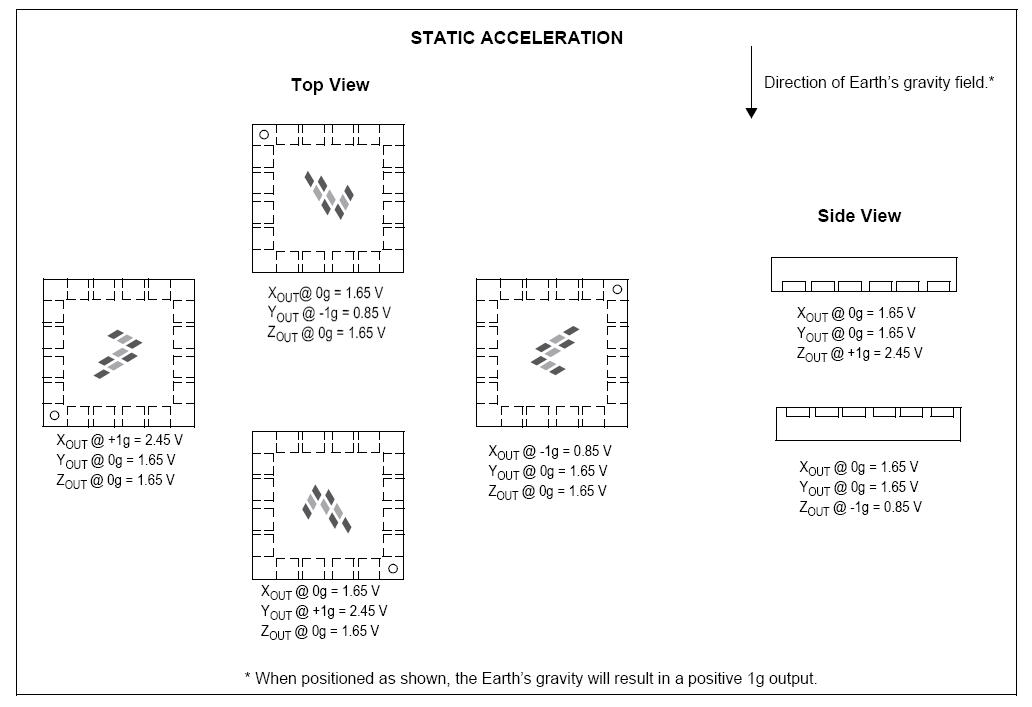
To explain briefly, in case of 1.5g by standard of 1.65V, value of voltage will change to 800mV/g. In case of 1g, g is an abbreviation of gravity and means acceleration of gravity. http://www.newtc.co.kr/board/view.phpid=pds&page=1&sn1=&divpage=1&sn=off&ss=on&sc=off&keyword=formula&select_arrange=headnum&desc=asc&no=121 That is to say, you can gain the value of voltage from the axis of X, Y and Z respectively. In case of 0g, you can get 1.65V. In the mode of 1.5g, output voltage per g changes by roughly 800mV. The module is manufactured so that it is basically set to the mode of 1.5g even if nothing is connected to gSelect. Of course, if you change the mode, the module will operate by the altered mode. And Z axis will be 1g in case of parallel placement. Therefore, we can gain 1.65V + 800mV = 2.45V. Even if we set to 0g, as a matter of fact, it is difficult to set an exact parallel. In this case, offset error can occur. The chip was very accurate at that time when it was manufactured because the chip is cut by laser in producing but, slightly an error can occur resulting from transportation, mechanic stress and temperature. If you read the manual linked below, you can see the same information.
However, algorithm to compensate this error is needed for this situation. First, you need to set 0g. Every chip can have different condition and the condition of the chip can be changed if it is given much stress after it was produced. For this reason, it is recommended that you prepare for function for the purpose of offset error correction to control 0g provided that 0g is an important issue. However exactly the chip may be placed on the flat ground, actually the chip can be inclined slightly and so you can take 0g which is an intermediate point of them getting the least value and the highest value if you turn slowly on each axis to the direction by one cycle. There are other ideas and please read the manual for them. In addition, it is recommended that you try to read the datasheet of MMA7260Q for exact utilization. |
|


