1. TheSpecification of RL78 small module (RM-RL78-G13)
-
RL78/G13 Prototyping module
-
It can be used maximum 32MHz using on-chip oscillator. In addition, equippedwith 32.768kHz X-tal for the clock correction and the RTC, and an externalclock up to 20MHz X-tal. You can connect and disconnect each clock source byconnecting a jumper or not.
-
Built-in multi-purpose connector. Using the E1 emulator, you canwrite your binary to target board and debug it, and also you can write thebinary by the programmer(RD-RL78-FP) using 1-Wire UART specification.
-
Built-in testswitch(P14 D0, Should be internal pull-up for active high operation)
-
At P7 D0~D3 pin,testing led is also equipped. It works as Active-High, and You can connect and disconnect each pin connection to led byconnecting a jumper or not
-
Power connector J8can work with 1.8 ~ 5.5V. If voltage is changed, then operation voltage andcurrent of I/O pin will be changed, also.
48 pins are arranged oneach pin 24 to the left or right. By this arrangement, you can study togetherwith breadboard mounting.
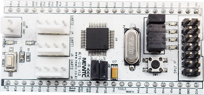
RM-RL78-G13 module (TOP)

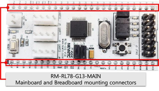
RM-RL78-G13module (BOTTOM)
1. HardwareSpecification
1.1. Hardware Configuration

The hardwareconfiguration of RM-RL78-G13 module (1/3, TOP)
The hardwareconfiguration of RM-RL78-G13 module (2/3, TOP)

The hardwareconfiguration of RM-RL78-G13 module (3/3, BOTTOM)
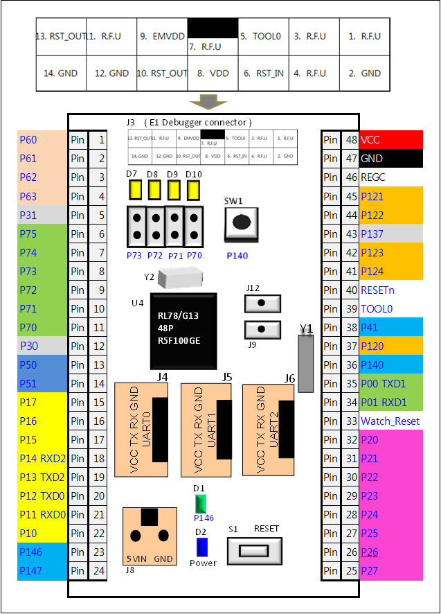
1.2. Pinouts
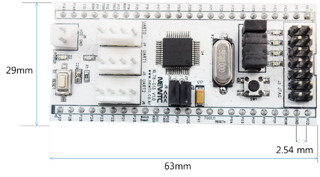
1.3.Mechanical specification
|