


- 트위터,페이스북


- HOME
- SHOPLIST
- RENESAS


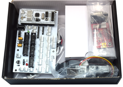
A kit with that needed for Renesas' RL78 series development RL78 / G13.1. Description- Renesas RL78 / G13 is a microcontroller development kit.- The kit can be packed to see the minimum components needed to develop and try to develop willingly.- Renesas's World Aliance Partner and the exclusive design house of educational products NEWTC technical support.2. SpecificationsA. that includes a programmable flash programmer via USB.B. serial port of TTL Level are integrated on board. (It can be changed according to a CMOS level to the global power supply of the operating voltage of the module and the board)C. RL78 General GPIO port of the development board, 10 are connected to the box-pin header.3. Model Photo
|