


- 트위터,페이스북


- HOME
- SHOPLIST
- RENESAS


Renesas' RL78 microcontroller training kit is to learn the RL78 / G13 series.
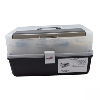
1. Description- Renesas RL78 / G13 microcontrollers are learning kits.- It inside a plastic bag for easy storage.- Contains a practical textbook for beginners convenient to education.- Renesas's World Aliance Partner and the exclusive design house of educational products NEWTC technical support.2. SpecificationsA. In that E1 is included in a program to a USB flash programmer and the RL78 programming / debugging equipment.B. serial port of TTL Level are integrated on board. (It can be changed according to a CMOS level to the global power supply of the operating voltage of the module and the board)C. Communication USB to Serial (UART) included the board.D. RL78 development boards and I / O board is connected to the box straight 2.54mm 10-pin header.E. Korean Language RL78 included that allows you to quickly perform development.F. All individual modules and boards provides each product Korean manual.3. Model Photo
|